Erode a Grayscale Image#
See also
erosion; dilation
Synopsis#
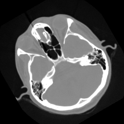
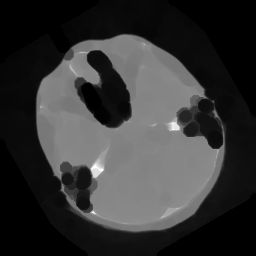
Erode regions by using a specified kernel, also known as a structuring element. In this example, the white regions shrink.
Results#

Input grayscale image.#

Eroded output.#
Code#
Python#
#!/usr/bin/env python

import sys
import itk
import argparse

itk.auto_progress(2)

parser = argparse.ArgumentParser(description="Erode A Grayscale Image.")
parser.add_argument("input_image")
parser.add_argument("output_image")
parser.add_argument("radius", type=int)
args = parser.parse_args()

PixelType = itk.UC
Dimension = 2

ImageType = itk.Image[PixelType, Dimension]

ReaderType = itk.ImageFileReader[ImageType]
reader = ReaderType.New()
reader.SetFileName(args.input_image)

StructuringElementType = itk.FlatStructuringElement[Dimension]
structuringElement = StructuringElementType.Ball(args.radius)

GrayscaleFilterType = itk.GrayscaleErodeImageFilter[
    ImageType, ImageType, StructuringElementType
]
grayscaleFilter = GrayscaleFilterType.New()
grayscaleFilter.SetInput(reader.GetOutput())
grayscaleFilter.SetKernel(structuringElement)

WriterType = itk.ImageFileWriter[ImageType]
writer = WriterType.New()
writer.SetFileName(args.output_image)
writer.SetInput(grayscaleFilter.GetOutput())

writer.Update()
C++#
#include "itkImage.h"
#include "itkImageFileReader.h"
#include "itkImageFileWriter.h"
#include "itkGrayscaleErodeImageFilter.h"
#include "itkFlatStructuringElement.h"

int
main(int argc, char * argv[])
{
  if (argc < 4)
  {
    std::cerr << "Usage: " << std::endl;
    std::cerr << argv[0] << " <inputImage> <outputImage> <radius>";
    std::cerr << std::endl;
    return EXIT_FAILURE;
  }
  const char *       inputImage = argv[1];
  const char *       outputImage = argv[2];
  const unsigned int radiusValue = std::stoi(argv[3]);

  using PixelType = unsigned char;
  constexpr unsigned int Dimension = 2;

  using ImageType = itk::Image<PixelType, Dimension>;

  const auto input = itk::ReadImage<ImageType>(inputImage);

  using StructuringElementType = itk::FlatStructuringElement<Dimension>;
  StructuringElementType::RadiusType radius;
  radius.Fill(radiusValue);
  StructuringElementType structuringElement = StructuringElementType::Ball(radius);

  using GrayscaleErodeImageFilterType = itk::GrayscaleErodeImageFilter<ImageType, ImageType, StructuringElementType>;

  auto erodeFilter = GrayscaleErodeImageFilterType::New();
  erodeFilter->SetInput(input);
  erodeFilter->SetKernel(structuringElement);

  try
  {
    itk::WriteImage(erodeFilter->GetOutput(), outputImage);
  }
  catch (const itk::ExceptionObject & e)
  {
    std::cerr << "Error: " << e << std::endl;
    return EXIT_FAILURE;
  }

  return EXIT_SUCCESS;
}
Classes demonstrated#
-
template<typename TInputImage, typename TOutputImage, typename TKernel>
class GrayscaleErodeImageFilter : public itk::KernelImageFilter<TInputImage, TOutputImage, TKernel> Grayscale erosion of an image.
Erode an image using grayscale morphology. Erosion takes the maximum of all the pixels identified by the structuring element.
The structuring element is assumed to be composed of binary values (zero or one). Only elements of the structuring element having values > 0 are candidates for affecting the center pixel.
- See
MorphologyImageFilter, GrayscaleFunctionErodeImageFilter, BinaryErodeImageFilter
- ITK Sphinx Examples:
-
template<unsigned int VDimension>
class FlatStructuringElement : public itk::Neighborhood<bool, VDimension> A class to support a variety of flat structuring elements, including versions created by decomposition of lines.
FlatStructuringElement provides several static methods, which can be used to create a structuring element with a particular shape, size, etc. Currently, those methods enable the creation of the following structuring elements: ball, box, cross, annulus, or polygon. Polygons are available as fast approximations of balls using line decompositions. Boxes also use line decompositions.
“Flat” refers to binary as opposed to grayscale structuring elements. Flat structuring elements can be used for both binary and grayscale images.
A Neighborhood has an N-dimensional radius. The radius is defined separately for each dimension as the number of pixels that the neighborhood extends outward from the center pixel. For example, a 2D Neighborhood object with a radius of 2x3 has sides of length 5x7. However, in the case of balls and annuli, this definition is slightly different from the parametric definition of those objects. For example, an ellipse of radius 2x3 has a diameter of 4x6, not 5x7. To have a diameter of 5x7, the radius would need to increase by 0.5 in each dimension. Thus, the “radius” of the neighborhood and the “radius” of the object should be distinguished.
To accomplish this, the “ball” and “annulus” structuring elements have an optional flag called “radiusIsParametric” (off by default). Setting this flag to true will use the parametric definition of the object and will generate structuring elements with more accurate areas, which can be especially important when morphological operations are intended to remove or retain objects of particular sizes. When the mode is turned off (default), the radius is the same, but the object diameter is set to (radius*2)+1, which is the size of the neighborhood region. Thus, the original ball and annulus structuring elements have a systematic bias in the radius of +0.5 voxels in each dimension relative to the parametric definition of the radius. Thus, we recommend turning this mode on for more accurate structuring elements, but this mode is turned off by default for backward compatibility.
As an example, a 3D ball of radius 5 should have an area of 523. With this mode turned on, the number of “on” pixels is 515 (error 1.6%), but with it turned off, the area is 739 (error 41%). For a 3D annulus of radius 5 and thickness 2, the area should be 410. With this mode turned on, the area is 392 (error 4.5%), but when turned off it is 560 (error 36%). This same trend holds for balls and annuli of any radius or dimension. For more detailed experiments with this mode, please refer to the results of the test itkFlatStructuringElementTest.cxx or the wiki example.
- ITK Sphinx Examples:
- ITK Sphinx Examples:
